|
|
NEWS
ntroduction of steel - aluminum composite contact rail for safety sliding contact line
2016-08-07
The standard main-line contact rails are placed on the insulation bracket device according to the nominal distance of 3 ~ 5 meters (the allowable tolerance of bracket positioning is ±10 mm). Note: in special areas, such as station, turning point, bend, ramp or expansion joint, the distance between insulation support devices should not be less than 3m.
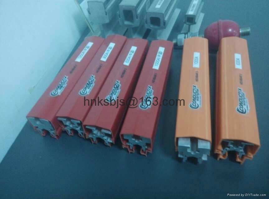
The steel-aluminum composite contact rail is composed of light-weight conductive aluminum rail body and very wear-resistant stainless steel contact surface. The rail body is made of high strength corrosion resistant aluminum alloy (6101-t6) extruded. The contact surface is a continuous 6mm thick stainless steel strip. The stainless steel belt is mechanically combined with the conductive aluminum rail to ensure the metal bonding between them, thus ensuring a small contact resistance between the aluminum and stainless steel belt. At 20℃, the dc resistance of the composite rail does not exceed 8.5 mm/m. The supply length of the composite rail is 15 meters, the weight of each 3000A contact rail is about 218kg, and the length is 15m.
The common joint of steel and aluminum composite contact rail for safety sliding contact wire is suitable for fixing adjacent contact rail and conducting current. The joint holes of the composite rail and the fishplate have minimum tolerances, so that only small or almost no mutual movement can be ensured in the mutual fit. The joints of contact rails shall be installed in a flush manner to ensure that one side of the stainless steel belt is installed in a flush manner and no uneven or torsion phenomena are allowed. The installation accuracy is 0.5mm.
The expansion joint is designed so that it can adapt to thermal expansion and cold contraction caused by environmental temperature change, temperature rise caused by electric current, sunshine and movement of composite rail. Expansion joint components are required to be aligned with the contact surfaces between adjacent tracks to ensure smooth passage of electric boots.
The safety sliding contact wire expansion joint is 1975mm long. In the straight section, the expansion joint shall be installed in the center of the two support devices as far as possible, and the distance between each end of the minimum expansion joint and the support device shall be no less than 400mm. If the expansion joint is set in the bend section, the insulation support and expansion joint will be subject to great tension. The sliding block of the expansion joint will wear out faster because of this extra tension, and the insulation bracket will wear out quickly.
So generally do not set up at the corner expansion joint. Under special circumstances, expansion joints must be set at curves with a radius less than 300m. At this time, expansion joints can still play a role, but the tension transfer that causes expansion joints to open and close ACTS on the insulation support. Given the distance between the anchors, this should be taken seriously.
In addition to connecting two independent steel and aluminum composite rails, the intermediate connector is also used to introduce external current to the contact rail. Each intermediate connector can connect 8 to 12 240mm2 wires. The conductor must have sufficient margin to avoid applying additional force to the composite rail, thereby preventing the longitudinal movement of the composite rail.
There are two types of end elbows for safe sliding contact line according to main line and yard line. The length of main line elbow is 5.2m, and the height difference at both ends of end elbow is 126mm. The length of the bend in the car yard is 3.4m, the height difference between the two ends of the end bend is 129mm, and the end bend and the contact rail are connected by common joints. Its function is to ensure that the electric boots can smoothly contact and disengage from the composite track when the train is running at the rated speed.
|